
How to Choose a Cartridge Filling Machine for Different Cartridge, Pod, and Disposable Formats
Why Hardware Format Affects Filling Equipment
Names such as “510 cartridge,” “pod,” and “disposable vape” describe broad product categories. They do not define a universal body shape or filling process.
A cylindrical cartridge may fit upright in a compact tray, while a flat or irregular pod may require a shaped pocket to prevent movement. An all-in-one disposable can have an offset filling port, a taller body, or a mouthpiece that needs to be installed soon after filling. Even devices with the same nominal oil capacity may require different needles, tray spacing, nozzle coordinates, and capping operations.
For this reason, equipment compatibility should be evaluated through measurable hardware information.
| Hardware factor | Why it affects machine selection | Information to provide |
|---|---|---|
| Overall dimensions | Determines tray size, pocket spacing and machine clearance | Length, width, height and body diameter |
| Filling-port position | Determines the nozzle coordinates and approach direction | Centered or offset position and distance from the body edges |
| Filling-hole diameter | Affects needle diameter and insertion clearance | Diameter in millimeters |
| Target fill volume | Determines the required dosing range | Required volume in ml |
| Device orientation | Influences fixture design and loading method | Upright, angled or horizontal |
| Mouthpiece or cap type | Determines the required closing process | Screw, press, plug or snap-fit |
| Body shape | Affects whether a standard tray can hold the device securely | Cylindrical, rectangular, tapered or irregular |
| SKU variation | Determines changeover frequency and tooling requirements | Number of formats and typical batch size |
The machine dimensions shown on a product page describe the equipment itself, not the compatible cartridge or pod size. Similarly, a dosing range such as 0.2–2 ml indicates how much material the machine can dispense; it does not confirm whether a particular device body will fit the tray.
Matching Equipment to Cartridges, Pods, and Disposables
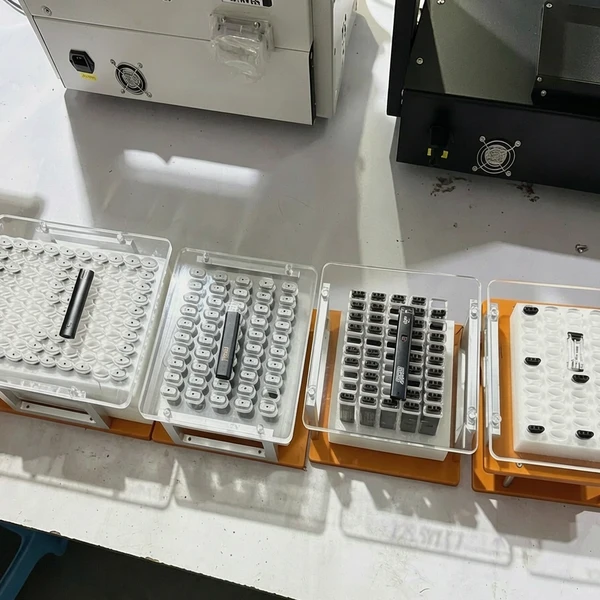
510 Cartridges and Vape Pens
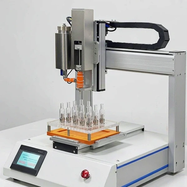
The 510 designation describes the connection type, but it does not define the complete cartridge geometry. Cartridge length, body diameter, mouthpiece structure, filling-hole size and center-airway position can still vary.
For tray-based automatic filling, the cartridge must sit securely and consistently in every pocket. The filling program must also align the needle with each opening without contacting the airway or the edge of the cartridge. If the device body is too loose in the tray, small position differences can affect needle access across a full batch.
A buyer should therefore provide both the cartridge and mouthpiece rather than submitting only the nominal capacity. A 1 ml cartridge should not be assumed to fit a fixture created for another 1 ml model.
Closed and Refillable Pods
Pods are frequently wider and less uniform than cylindrical cartridges. Their filling ports may sit near an edge, beneath a removable plug, or beside an internal airway. Some pods can remain upright without support, while others require a contoured tray to control their position.
For automatic filling, the fixture must hold each pod in the same orientation and leave enough clearance for the nozzle. A pod that can be filled manually may still require a dedicated tray for consistent automatic operation.
When several pod models will share one machine, determine whether each SKU needs a separate tray and filling program. Interchangeable tooling may be practical, but the time required to replace the tray, adjust the needle and confirm the first filled units should be included in the changeover assessment.
All-in-One and Disposable Devices
An all-in-one disposable combines the reservoir, battery section and mouthpiece in a single body. Its additional height and width can affect tray loading, nozzle clearance and movement between filling and closing stations.
The filling port may also be offset or surrounded by structural components. This makes the filling-hole position just as important as the device’s overall dimensions. For multi-nozzle equipment, the spacing between devices and the alignment of each filling port must match the machine configuration.
Do not select a disposable vape filling machine from capacity alone. A machine with a suitable dosing range may still need a customized fixture, different needle position or additional clearance for the complete disposable body.
Longwill Filling Machine Selection Matrix
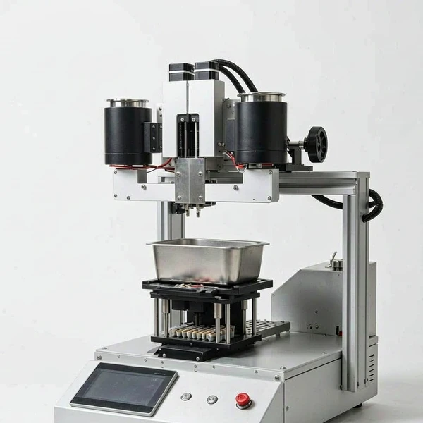
The table below is intended for initial equipment screening. The published filling ranges describe dosing capacity rather than universal hardware dimensions. Exact cartridge, pod or disposable compatibility should be confirmed with samples or drawings.
| Model | Suitable purchasing scenario | Published filling range | Published output | Main hardware consideration |
|---|---|---|---|---|
| FM-07 Auto Robo Cartridge Filling Machine | Tray-based automatic filling for cartridges, pens and similar hardware | 0.2–2 ml; additional configurations shown up to 10 ml | 800–1,200 pcs/hour | Uses customized trays and programmed filling positions |
| FM06 Auto Filling Machine | Multi-nozzle filling for carts, pods, pens and small bottles | 0.2–2 ml, 0.2–5 ml or 0.2–10 ml | 1,800–2,500 pcs/hour | Six-nozzle arrangement requires verified tray spacing and filling-port alignment |
| FM09 Smart Filling Machine | Flexible dosing for products requiring a wider filling-volume range | 0.2–2/5/10/20 ml | 800–1,500 pcs/hour | Hardware body dimensions and positioning method must be confirmed separately |
| FM10 Smart Cart Filling Machine | Small and medium batches with operator-controlled device handling | 0.2–2 ml | 800–1,500 pcs/hour | Manual positioning offers flexibility for changing filling-port locations |
| FC-01 Filling and Capping Machine | Integrated filling and capping for stable, repeated production | 0.2–2 ml; another configuration is shown up to 5 ml | 800–1,500 pcs/hour | Filling fixture and capping structure must both match the device |
Published output figures are equipment ratings rather than guaranteed production results. Actual throughput can change with the material condition, target dose, number of active nozzles, operator pace, tray loading method, SKU changeovers and closing process.
Automatic or Semi-Automatic Filling
An Automatic Cartridge Filling Machine is generally more suitable when the device format, material and batch plan are stable. Once the tray and filling program have been prepared for the approved hardware, the machine can repeat the same positioning and dosing sequence across longer runs.
However, automation depends more heavily on fixtures. A new device shape, filling-hole position or body dimension may require another tray or program. If the production schedule includes many small orders, the time spent changing and validating tooling can reduce the practical advantage of a higher rated speed.
A semi automatic cartridge filling machine is often more appropriate for product development, sample production, frequent formula changes or multiple hardware formats. Because the operator positions the device and controls the filling step, it can be easier to accommodate different filling-port locations without creating a full automatic tray arrangement for every SKU.
| Production condition | Recommended starting point | Selection reason |
|---|---|---|
| One stable device with repeated large batches | Automatic tray-based filling | Stable hardware makes fixture-based automation practical |
| Several devices with frequent changeovers | Semi-automatic filling | Reduces dependence on a dedicated tray for every format |
| Irregular pod or disposable body | Hardware test before machine selection | Body shape and port access may require customized support |
| Dual-oil or dual-flavor device | Dual-channel filling configuration | Separate material paths and adjustable needle spacing may be required |
| Filling and capping in one workflow | Integrated filling and capping equipment | Both the dispensing and closing stages must match the hardware |
| Hardware design is still changing | Semi-automatic trial setup | Avoids finalizing automatic tooling around an unfinished device |
The correct automation level is therefore not determined by hourly output alone. It should reflect the stability of the product design and the way orders are organized in daily production.
Include Changeovers in the Equipment Comparison
Maximum speed describes only the running stage. A realistic purchasing comparison should also consider the time required to move from one device or material to another.
A hardware change may involve replacing the tray, selecting another filling program, adjusting nozzle coordinates, changing the needle and confirming the first few units. A material change can add cleaning or oil-path preparation. If the second product uses a different mouthpiece, the capping station may require its own adjustment.
For plants handling many SKUs, changeover time can have a greater effect on daily output than the difference between two machine speed ratings. When requesting a recommendation, provide a representative schedule rather than only a daily production target. For example, explain how many device models are filled per shift, the typical batch size and how often the oil formula changes.
This allows the machine configuration to be evaluated against the actual workflow instead of an ideal single-SKU production run.
Filling Compatibility Does Not Confirm Capping Compatibility
Filling and capping rely on different parts of the device. A cartridge may fit correctly in a filling tray but require different support, force or motion when the mouthpiece is installed.
Screw-on mouthpieces need controlled rotation and suitable torque. Press-fit components require alignment, pressure and support beneath the cartridge or disposable body. Plugs and snap-fit components can introduce different access and positioning requirements.
Longwill’s CM-05 and TM03 capping models publish an applicable cartridge length of 20–110 mm. This dimension provides an initial screening range, but length alone does not confirm that a mouthpiece can be closed correctly. The cap type, thread, body support point and required torque or pressure must also be tested. For integrated filling and capping, see the Cartridge Capping Machine range.
For integrated filling and capping, send the complete device assembly rather than only the empty reservoir. The evaluation should include the body, mouthpiece, plug and any component installed immediately after filling.
What to Send for a Compatibility Review
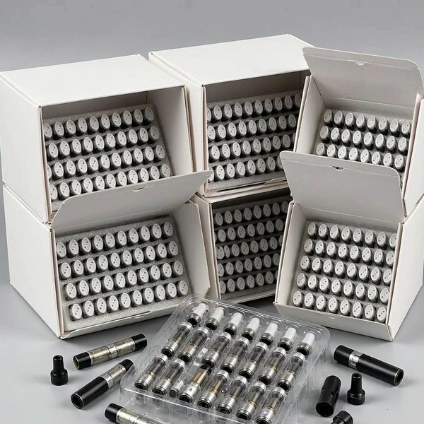
A complete project package reduces uncertainty and makes it easier to identify whether a standard machine configuration is suitable. It also helps determine which trays, needles, programs or capping fixtures need to be included in the quotation.
Provide several empty hardware samples together with dimensioned drawings. The drawings should show the overall body size, filling-hole diameter, filling-port location and internal airway position where relevant. Include the mouthpiece or cap and explain how it is installed.
The equipment supplier will also need the target fill volume, planned material, expected batch size, number of SKUs and preferred automation level. If material viscosity changes with operating conditions, provide the conditions expected during production rather than only a general material name.
The following information should be prepared before the final equipment recommendation:
- Complete hardware samples, including the body, plug and mouthpiece
- Overall dimensions and filling-port location
- Target dose and acceptable filling tolerance
- Material information under the planned filling conditions
- Expected units per batch, shift and day
- Number of hardware SKUs and changeover frequency
- Required closing method
- Available voltage, compressed air and production space
Drawings and photographs can support an initial assessment when samples are not yet available. Final fixture approval should still use production hardware because molding variation, surface shape and assembly tolerances may not be fully represented in a drawing.
How to Evaluate a Sample Filling Test
A useful filling test should reproduce the intended production conditions as closely as possible. It should use the planned device, target dose and representative material rather than a different container or an easier-flowing substitute.
During the test, check whether the hardware remains stable in the fixture and whether the needle reaches the filling chamber without contacting the airway or device wall. Review multiple filled units to determine whether positioning remains consistent across the tray.
For automatic equipment, the evaluation should include tray loading, program selection, filling, unloading and changeover. If the machine is expected to handle more than one device, repeat the relevant steps with each format rather than assuming that the first successful test applies to every SKU.
For a filling-and-capping configuration, mouthpiece installation should be included in the same test. This verifies whether the filled device can move through the complete workflow without requiring an unplanned manual step.
Final Purchasing Checklist
Before placing an order, confirm the agreed configuration in the quotation or technical document.
| Item to confirm | Why it matters |
|---|---|
| Approved hardware model and revision | Prevents a redesigned device from being treated as the same format |
| Fixture or tray drawing | Defines how the hardware will be held |
| Number of trays included | Affects loading continuity and changeover planning |
| Needle specification and nozzle count | Determines filling-port access |
| Approved filling range | Confirms that the target dose is covered |
| Tested material and operating conditions | Keeps the test relevant to production |
| Capping method and supported dimensions | Separates filling compatibility from closing compatibility |
| Change parts for each SKU | Clarifies additional tooling and cost |
| Acceptance-test conditions | Defines what will be checked before shipment |
| Utilities and installation requirements | Prevents site-preparation delays |
The final choice should match the complete combination of hardware, material, dose, production plan and closing method. A general format name can narrow the initial options, but physical samples and drawings are what determine whether a specific configuration is suitable.
FAQ
Can one cartridge filling machine handle cartridges, pods, and disposable devices?
A machine may be configured for more than one format, but this depends on the dimensions, filling-port position, fixture and needle access of each device. Separate trays or saved filling programs may be required. Compatibility should be confirmed for each hardware model rather than assumed from category names.
Does a 1 ml cartridge fit every machine designed for 1 ml hardware?
No. The 1 ml figure describes the cartridge capacity, not its body dimensions. Two 1 ml cartridges can have different diameters, lengths, mouthpieces and filling-hole locations. The machine’s dosing range and the fixture’s physical compatibility must be checked separately.
What dimensions are needed for a pod or disposable vape?
Provide the overall length, width, height and body diameter where applicable. Also include the filling-hole diameter and its position relative to the device edges. Mouthpiece dimensions, cap type and internal airway location should be supplied when they affect filling or closing.
Is automatic equipment suitable for production with multiple SKUs?
It can be, provided suitable trays, filling programs and change parts are prepared for each SKU. Buyers should compare the practical changeover process as well as the rated filling speed, especially when production consists of several small batches.
Does filling-machine compatibility guarantee capping compatibility?
No. Filling and capping involve different device contact points. The mouthpiece structure, device length, supporting position, thread or press-fit design and required force or torque must be evaluated separately.
Can compatibility be confirmed from drawings alone?
Drawings can support initial selection and fixture planning, but physical samples provide stronger confirmation of fit, needle access and dimensional variation. Final approval should use the production hardware together with the intended mouthpiece or cap.
Choose Equipment Around Your Actual Hardware
To evaluate a filling setup, provide Longwill with your hardware samples or dimensioned drawings, target filling volume, material information, expected batch size and closing method. The machine, tray, needle arrangement and capping process can then be reviewed as one production system rather than as separate equipment specifications.
Table of Contents